- Home
- Oilfield Equipment CATALOGUE
- Wellhead & Christmas Tree
- Well Control Equipment
- Mud Logging Unit
- Mud Pump & Spares
- Top Drive Drilling Equipment
- Formation tester
- Multiphase-Flow-Meter(MFM)
- New Research & Design Tools
- Blade Retrievable New-type Scraper (Patent product)
- Down-hole Safety Valve
- Dual Reverse Circulating Valve
- Full bore Pressure Controlled Select Tester Valve
- New-type Dual Sealing Multi-function Hydraulic Packer (Patent product)
- New-type Dual Sealing Multi-function Mechanical Packer (Patent product)
- New-type MFC Clean & Scrape Integrated Operation Tool and String Selection (Patent product)
- New-type MFC Drill and Scrape Integrated Operation Tool and String Selection (Patent product)
- Wellhead Hydraulic Safety Valve
- Packer
- Well Testing & Completion Tools
- Well Workover Tools
- Wellhead Tools
- Drilling tools
- Casing Bushing And Insert Bowl series
- DG Series Of Hooks
- DWJ-178/250 Power Slips
- Dslseries Power Swivels
- FP sealed anti-spraying boxes
- FSQ Mouse Hole Clamping Device
- Hydraulic Pneumatic Spinner
- JGS-1B Geophysical Well Logging Equipment
- Kelly Spinner
- PZ Series Of Mud Pump
- Pneumatic reversing valve
- Q Series Of Spinning
- QD Pneumatic Casing
- QJ Series Air Winches
- QW Series Drill Pipe Air Slips
- Roller Kelly Bushing
- Rotary Bushing And Insert
- Suspender
- Swivel With Spinner
- TB casing back-up tong
- TC SERIES OF CROWN BLOCKS
- TF Series Of Casing Guides
- TJA Series Casing And Tubing coupling bucking unit
- TJX Series Of Mandrel
- TQ Series Casing Tong
- TS Series Of Hydraulic Riser
- XQ Series of Hydraulic Power Tongs
- YC Series Of Traveling
- YG SERIES OF HOOK BLOCKS
- YJ Series Hydraulic Winches
- YM Series Hydraulic Cathead
- YXM Rotary Cathead
- YZB(YZC) Series Of Hydraulic Power Unit
- ZP Series Of Rotary Tables
- ZQ Drill Pipe Power Tongs
- ZQF216-110 lron roughneck
- ZQJ178 90 drill pipe screwing tong
- ZTQ SERIES DUAL-PURPOSE POWER TONGS
- Drill collars / Drill pipes
- Elevators / Slips / Spiders
- ACCESSORY TOOLS
- CEMENTING TOOLS
- Coring Tools
- DRILL STEM TOOLS
- Arrow Type Back Pressure Valve
- By-pass Valve
- Casing Scraper
- Circulating Sub
- Cup Tester
- Drift
- Drop-In Check Valve
- Fixed Diameter Hole Opener
- Float valve sub
- Full Opening Safety Valve
- Inside BOP
- Integral blade stabilizer
- Kelly Valve
- Key seat Reamer
- Lifting cap and Casing Protector
- Non-rotating Stabilizer
- Oriented Bent sub
- Replaceable Sleeve Stabilizer
- Roller Reamer
- Rotary Sub And Others
- Wear Sub
- Drill Collar
- Drill Pipe
- FISHING TOOLS
- AJ Type Safety Joint
- Cable Fishhook
- Die Collars
- Ditch Magnet
- External Hook
- H Type Safety Joint
- Impression Blocks
- Internal Hook
- Junk Subs
- Lifting-Lowering and Releasing Overshots
- Mechanical External Cutter
- Mechanical Internal Cutter
- Multi-String Cutter
- Releasing Spear
- Releasing and Reversing Overshots
- Reverse Circulation Fishing Magnet
- Reverse Circulation Junk Basket
- Reversing Spear
- Reversing sub
- Section Mill
- Series 20 Overshort
- Series 70 Short Catch Overshot
- Sliding Block Spear
- Standard Fishing Magnet
- Taper Tap
- Washover Pipe
- series 150 overshot
- Integral Heavy Weight Drill Pipe
- JARS TOOLS
- BXJ Lubricated fishing bumper sub
- CSJ Super Fishing Jar
- DJ Surface Bumper Jar
- JYSZ Double Acting Hydraulic-Mechanical Drilling Jar
- KXJ Fishing Bumper Sub
- QJZ Mechanical Drilling Jar
- QYSZ Type Full Hydraulic Drilling Jar
- SJ Double-Way Shock Absorber
- YJ one-way shock absorber
- YSJ Type Z Oil Jar
- ZJS Jar Intensifier
- ZSJ/ZXJ Hydraulic & Mechanical
- Kellys & tool joints
- MILLING TOOLS
- Kelly / Bushings
- Search
- About
- Supply Chain Management
- Global Reach
- Contact
Packer Equipment Sourcing
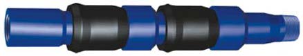
Z331 Double Rubble Bowl Packer
-
Usage
This type of Packer is composed by two rubber bowls with steel bone. It could be used in single string well which differential pressure is normally, not need to set, could seal by differential pressure or friction between rubble bowls and casing surface. Also could be used in low differential pressure shallow well, pressure could be balanced or anchor well, or well flushing and preventing of pollute oil layer technique. Rubber bowls could be changed as technical requirement.- Without anchor structure, could be used in vertical well, slope well and horizontal well. No control for operation grade.
- Two rubber bowl could be opposite (keep pressure from two sides), or could be same direction. Rubber bowls could be assembled at any direction, and disassemble conveniently.
-
Run with string tools to seal tubing & casing annulus, no need of other power plant, which could save operation time and cost.
-
Structure feature
Connect with other sting tools and run into well, when to determined depth position, could seal by compression of rubber bowls with casing surface and differential pressure. Pull up string tools when in workover operation. Rubber bowls bear single differential pressure, seal by rubber bowl and casing will be stronger as differential pressure increased. Make sure of bearing direction before running into well, in order to avoid of wrong direction of Packer.
-
Technical specification
Size 5’’ 5 1/2’’ 7’’ 7 5/8’’ 7 7/8’’ Max. OD. (mm) Ф113 Ф126 Ф162 Ф175 Ф183 Steel body Max. OD. (mm) Ф100 Ф112 Ф144 Ф157 Ф165 ID. (mm) Ф50 Ф50 Ф62 Ф76 Ф76 Length (mm) 518 518 626 680 680 Working circumstances Mud, crude oil, natural gas, water Working temperature (℃) 0~150 Working pressure (MPa) 15 Thread connecion 2 3/8 TBG B×B 2 7/8 TBG B×B 3 1/2 TBG B×B
Dual Locking Packer
-
Usage
Dual locking packer is one type of hanging packer which has a large ID, with bypass, and could seal double sides of pressure. By rotation and pull up & down string tools to set and unset, could be used in middle or shallow casing well for DST testing, acidification, cementing and etc.
-
Structure feature
Includes of special mechanical locking system and double slips structure, which could seal any pressure from top or bottom of Packer after setting and without increase drill pressure, if pull up of Packer, could not unset either.
-
Technical specification
Size 5 1/2’’ 7’’ Top shoe OD. (mm) Ф114, Ф118 Ф148, Ф152 Suitable casing size 5 1/2’’ 7’’ ID. (mm) Ф50 Ф57 Length (mm) (extension) 1168 1381 Working circumstances Mud, crude oil, natural gas, water Working temperature (℃) -29℃~180℃ Thread connecion 2 3/8 EUE B×P 2 7/8 EUE B×P
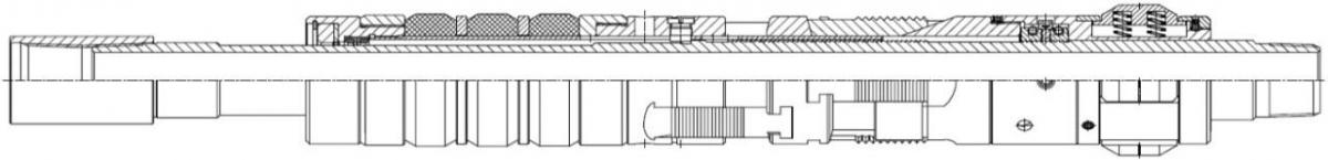
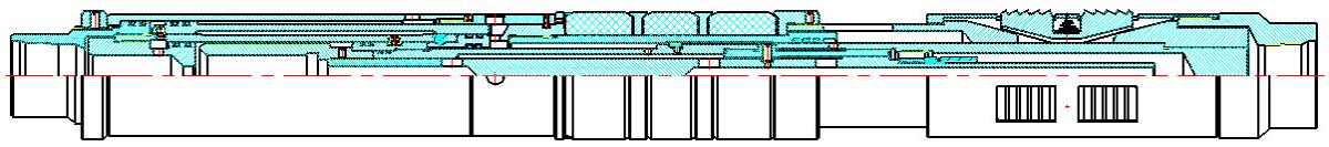
Retrievable Bridge Plug
Introduction
I. Introduction
Retrievable bridge plug is a down-hole plugging tool used in oilfield with hydraulic setting, stepped locking, bi-directional slips and special tools for unlocking, it featuring as follows:
- Going down into the hole easily: special design of hydraulic slip, which would not hamper the setting process when blocked in the down-hole, used in inclined and horizontal wells.
- Setting stably: special design of packing element structure, greatly improving the pressure tolerance of the bridge plug.
- Releasing off easily: every batch of products being strictly tested before delivery, with the rating releasing pressure.
- Bi-directional slips for firmly anchoring.
- Fishing out easily: special design of fishing mechanism, forcing the slips to reset, success rate of fishing out 100%.
- Being able to wash the well: the flushing passage for direct and inverse well-flushing when the tool going down the preset position.
II. Technical parameter
|
Type |
7 7/8" |
7 5/8" |
7" |
5 1/2" |
5" |
|---|---|---|---|---|---|
|
Max OD |
169 mm |
162 mm |
147 mm |
114 mm |
103 mm |
|
Applied casing |
7 7/8" |
7 5/8" |
7" |
5 1/2" |
5" |
|
Total length |
1627 mm |
1625 mm |
1500 mm |
1135 mm |
1025 mm |
|
Working temperature |
-20-180℃ |
-20-180℃ |
-20-180℃ |
-20-180℃ |
-20-180℃ |
|
Application environment |
Mud, crude oil, natural gas, water |
Mud, crude oil, natural gas, water |
Mud, crude oil, natural gas, water |
Mud, crude oil, natural gas, water |
Mud, crude oil, natural gas, water |
|
Setting pressure |
8-10 MPa |
8-10 MPa |
8-10 MPa |
8-10 MPa |
8-10 MPa |
|
Releasing pressure |
20-22 MPa |
20-22 MPa |
20-22 MPa |
20-22 MPa |
20-22 MPa |
|
Unsetting tonnage |
8-10 t |
8-10 t |
8-10 t |
8-10t |
8-10 t |
|
Thread connection |
2 7/8 UP TBG |
2 7/8 UP TBG |
2 7/8 UP TBG |
2 7/8 UP TBG |
2 7/8 UP TBG |
III. Structure and working principle
The retrievable bridge plug is composed primarily of the setting mechanism, sealing mechanism, unsetting mechanism and so forth; used with a unique automatic locking mechanism firmly withstanding bi-directional pressure.
Working principle:
- Setting and releasing: lower the bridge plug to the designed depth, locating the steel ball onto the surface of the ball seat and sealing the passage under the ball seat, then pressurize the tubing to about 8-10 MPa, cutting the setting shear pin and continuing pressurizing to force the piston sleeve downward against the setting piston, the fixing shear pin being cut and the setting piston moving downward with the element mandrel and the upper cones under pressure, thus sitting the slip anchor on the inside wall; continuing pressurizing, the element beginning to expand, when the pressure being about 20-22 MPa, the releasing shear pin being cut and the setting then being completed, with releasing achieved simultaneously. At the same time, the upper joint, outer element, connecting sleeve, ball seat, piston sleeve and so forth has not any rigid connection with the bridge plug body, so the upper portion can be easily pulled out, the locking ring being engaged with the buttress thread on the element mandrel, thus maintaining the element in the setting state.
- Unsetting: tubing goes down the special unsetting tool, seizing the bridge plug fishing head and picking up the tubing string, then cutting the unsetting shear pin and continuing picking up, the spring case being moved upward by the mandrel, separating the spring case from the blank mandrel, then continuing picking up, removing the automatic locking mechanism of the bridge plug, the element retracted and the slips retracted into the slip socket, thus unsetting the bridge plug, whose assembly being pulled out onto the surface with the tubing.
- Security measures: use a releasing fishing tool, rotating the tubing string to the right and retrieving the fishing tool when catching failure leads the bridge plug to be hardly retrieved. If the tool blocked in the casing and needing drilling and milling, a flat rolling-ball type milling shoe with surfacing YD alloy is recommended.
Matters should be noticed:
- Keep the components and parts clean before installation so as not to hamper the assembling, buttering the O-ring and threads; assuring the direction of the sawtooth buckle, being rotating-proof without a deformation.
- Ensure that the down hole is unobstructed before the bridge plug going down the hole, best to have a pigging and flushing before the bridge plug going down in an unclear situation.
- The going down speed of the bridge plug should be about 0.5m/s, the slips and element being away from the casing coupling.
- If the bridge plug gets stuck in a soft blockage or the liquid in the tubing hampers the falling of the steel ball, a direct and inverse flushing can be operated, but the pressure of the direct flushing should be controlled in 5MPa.
- When blocked during running in the fishing tool, a continuous sand flushing should be operated with running in the tubing string simultaneously until the fishing accomplishing.
-
A ventilated dry storage is not necessary, conventional oil sealing.
- « first
- ‹ previous
- 1
- 2
- 3