


- Home
- Oilfield Equipment CATALOGUE
- Wellhead & Christmas Tree
- Well Control Equipment
- Mud Logging Unit
- Mud Pump & Spares
- Top Drive Drilling Equipment
- Formation tester
- Multiphase-Flow-Meter(MFM)
- New Research & Design Tools
- Blade Retrievable New-type Scraper (Patent product)
- Down-hole Safety Valve
- Dual Reverse Circulating Valve
- Full bore Pressure Controlled Select Tester Valve
- New-type Dual Sealing Multi-function Hydraulic Packer (Patent product)
- New-type Dual Sealing Multi-function Mechanical Packer (Patent product)
- New-type MFC Clean & Scrape Integrated Operation Tool and String Selection (Patent product)
- New-type MFC Drill and Scrape Integrated Operation Tool and String Selection (Patent product)
- Wellhead Hydraulic Safety Valve
- Packer
- Well Testing & Completion Tools
- Well Workover Tools
- Wellhead Tools
- Drilling tools
- Casing Bushing And Insert Bowl series
- DG Series Of Hooks
- DWJ-178/250 Power Slips
- Dslseries Power Swivels
- FP sealed anti-spraying boxes
- FSQ Mouse Hole Clamping Device
- Hydraulic Pneumatic Spinner
- JGS-1B Geophysical Well Logging Equipment
- Kelly Spinner
- PZ Series Of Mud Pump
- Pneumatic reversing valve
- Q Series Of Spinning
- QD Pneumatic Casing
- QJ Series Air Winches
- QW Series Drill Pipe Air Slips
- Roller Kelly Bushing
- Rotary Bushing And Insert
- Suspender
- Swivel With Spinner
- TB casing back-up tong
- TC SERIES OF CROWN BLOCKS
- TF Series Of Casing Guides
- TJA Series Casing And Tubing coupling bucking unit
- TJX Series Of Mandrel
- TQ Series Casing Tong
- TS Series Of Hydraulic Riser
- XQ Series of Hydraulic Power Tongs
- YC Series Of Traveling
- YG SERIES OF HOOK BLOCKS
- YJ Series Hydraulic Winches
- YM Series Hydraulic Cathead
- YXM Rotary Cathead
- YZB(YZC) Series Of Hydraulic Power Unit
- ZP Series Of Rotary Tables
- ZQ Drill Pipe Power Tongs
- ZQF216-110 lron roughneck
- ZQJ178 90 drill pipe screwing tong
- ZTQ SERIES DUAL-PURPOSE POWER TONGS
- Drill collars / Drill pipes
- Elevators / Slips / Spiders
- ACCESSORY TOOLS
- CEMENTING TOOLS
- Coring Tools
- DRILL STEM TOOLS
- Arrow Type Back Pressure Valve
- By-pass Valve
- Casing Scraper
- Circulating Sub
- Cup Tester
- Drift
- Drop-In Check Valve
- Fixed Diameter Hole Opener
- Float valve sub
- Full Opening Safety Valve
- Inside BOP
- Integral blade stabilizer
- Kelly Valve
- Key seat Reamer
- Lifting cap and Casing Protector
- Non-rotating Stabilizer
- Oriented Bent sub
- Replaceable Sleeve Stabilizer
- Roller Reamer
- Rotary Sub And Others
- Wear Sub
- Drill Collar
- Drill Pipe
- FISHING TOOLS
- AJ Type Safety Joint
- Cable Fishhook
- Die Collars
- Ditch Magnet
- External Hook
- H Type Safety Joint
- Impression Blocks
- Internal Hook
- Junk Subs
- Lifting-Lowering and Releasing Overshots
- Mechanical External Cutter
- Mechanical Internal Cutter
- Multi-String Cutter
- Releasing Spear
- Releasing and Reversing Overshots
- Reverse Circulation Fishing Magnet
- Reverse Circulation Junk Basket
- Reversing Spear
- Reversing sub
- Section Mill
- Series 20 Overshort
- Series 70 Short Catch Overshot
- Sliding Block Spear
- Standard Fishing Magnet
- Taper Tap
- Washover Pipe
- series 150 overshot
- Integral Heavy Weight Drill Pipe
- JARS TOOLS
- BXJ Lubricated fishing bumper sub
- CSJ Super Fishing Jar
- DJ Surface Bumper Jar
- JYSZ Double Acting Hydraulic-Mechanical Drilling Jar
- KXJ Fishing Bumper Sub
- QJZ Mechanical Drilling Jar
- QYSZ Type Full Hydraulic Drilling Jar
- SJ Double-Way Shock Absorber
- YJ one-way shock absorber
- YSJ Type Z Oil Jar
- ZJS Jar Intensifier
- ZSJ/ZXJ Hydraulic & Mechanical
- Kellys & tool joints
- MILLING TOOLS
- Kelly / Bushings
- Search
- About
- Supply Chain Management
- Global Reach
- Contact
MPM
Multiphase Flow Meter MPFM ™
Technology Overview
 Multiphase Flow Meter MPFMs measure the flow rates of individual phases in oil, condensate and wet gas production lines without the need for separation or complex sensor technologies.
Multiphase Flow Meter systems are founded on a combination of traditional fluid flow theory and modern signal processing and neural network techniques.
Multiphase Flow Meter systems work with signals emitted by oil and gas industry standard sensors and do not require nuclear source sensors (only available as an option). The signals are processed in low power consumption computer installed on the flow line and the measurements are transmitted via the SCADA interface.
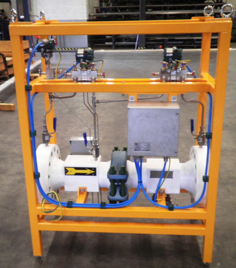
Electro - Mechanical System
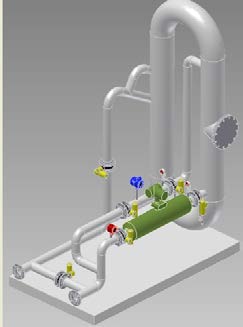
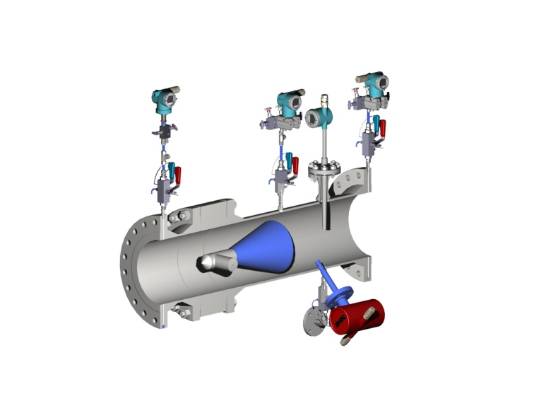 Multiphase Flow Meter spools are designed for compactness, durability, ease of maintenance and flexibility. The system comprises a number of modular sub-spools which are selected to suit given process requirements.
The Cone Spool contains two DP transmitters (one across the cone, the other measuring recovery pressure downstream), one AP transmitter and an RTD. The Cone also acts as a capacitance sensor for oil external applications and as a conductance sensor for water external applications. The spool is normally installed horizontally and the flow passes through the spool in a straight line with very low pressure drop.
The Coriolis Spool carries out mass flow rate and fluid density measurements independently (corrected by feed-back from the Cone Spool for multiphase effects).
The Gamma Ray Spool (option) employs a dual low energy source system. Gamma spool is capable of measuring water cut and GVF at the same time and replaces the impedance function integrated into the Cone Spool.
The Red Eye Spool (option) employs Weatherford Red Eye infra red absorption spectroscopy which can measure water cut independently. Red Eye is recommended in water continuous flow regime.
All Multiphase Flow Meter sensors are industry standard sensors chosen specially for rugged use. Further information about the sensors used in Multiphase Flow Meter can be found in detailed data sheets which are available on request.
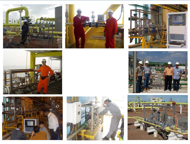
Application Areas
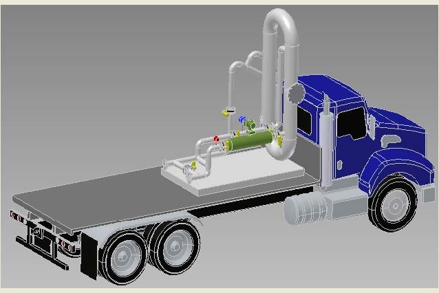
Multiphase Flow Meter MPFMs have been in use for over ten years in on-shore and off-shore fields across the globe. Multiphase Flow Meter MPFMs are ideally suited for well testing and allocation applications in fixed or mobile configurations. ESMER technology can be implemented for heavy or light oil multiphase flow or wet gas / condensate process conditions by the relevant combination of sensors and calibration algorithms.
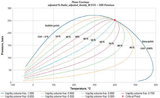
Hydrodynamic and Thermodynamic Flow Models
Multiphase Flow Meter MPFMs can be configured for use under a variety of fluid and flow regimes by means of a combination of adaptable hydrodynamic and thermodynamic models. Models are fine tuned against process conditions by means of neural nets.
Specification
Each Multiphase Flow Meter MPFM is built and calibrated to order to meet specific process and fluid requirements. Careful attention is paid to material selection to provide protection against corrosion. Multiphase Flow Meter MPFMs are quality tested by third party inspectors. We collaborate closely with TUV, Bureau Veritas, Lloyds to implement industry standards for testing and inspection during FAT testing of systems.
|
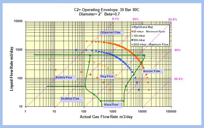
Operating Envelope |
Measurement Uncertainty |
|---|---|
|
Gas: Depends on pipe diameter |
Liquid flow rate: +/- 5% (relative) Quoted at 95% confidence level. Accuracy will depend on GVF, water composition and field tune-up capability. |
| Electro-Mechanics | ||||||||||||||||||||||||||||||
|---|---|---|---|---|---|---|---|---|---|---|---|---|---|---|---|---|---|---|---|---|---|---|---|---|---|---|---|---|---|---|
|
Materials, Flanges, Schedule: Built to NACE and ASME standards. Materials selected as per customer request. Meter sizes: 2” to 14“ Transmitters: Impedance/DP/AP/ RTD/Coriolis/Gamma/Infra Red Certification: EEx ia IIB T4 Power Supply: 24 VDC / 110/220 VAC / 20 W
|
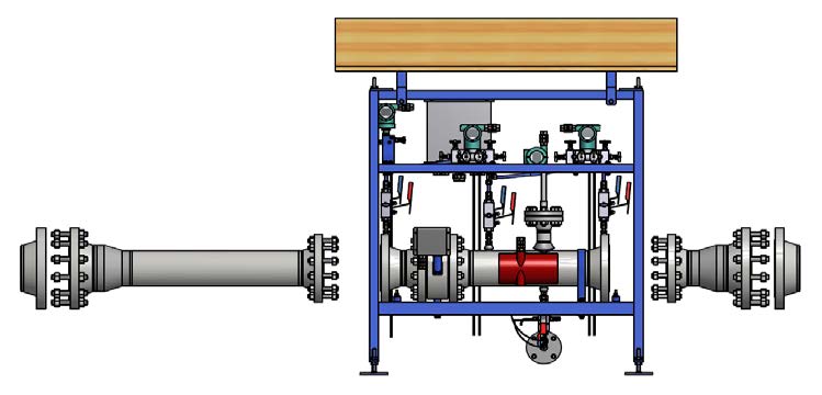
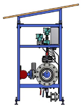
Multiphase Flow Meter C6+ GENERAL ARRANGEMENT DRAWING
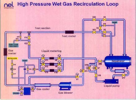
 Flow Loop Calibration & Performance Benchmark
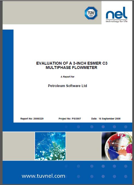
Multiphase Flow Meter MPFMs are calibrated / tested in a multiphase flow loop. NEL UK flow loop is commonly used.
NEL provides an independent performance report on request. Some examples of recent Multiphase Flow Meter MPFM NEL reports :
Evaluation of a 6 inch Multiphase Flow Meter C6 MPFM NEL Report 2013/386 August 2013
Evaluation of a 2-inch Multiphase Flow Meter C2 MPFM NEL Report 2012/580 16 November 2012
 Multiphase Flow Meter calibrations are carried out under conditions which provide the best match against particular process conditions.
Particular laboratories and calibration matrices will be recommended after a careful study of the process conditions and the operating envelope.
Field Calibration & Validation
Multiphase Flow Meter MPM is connected in series with Multiphase Flow Meter GLCC (passive controlled gas-liquid cylindrical cyclonic separator) or horizontal gravity separator (separator design will depend on process data) for in-field periodic validation and calibration tune up as per API 2566 guidelines
Multiphase Flow Meter GLCC
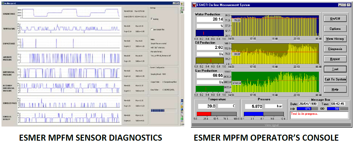
Flow Computer and Software
- Hazardous Area: Beckoff Microprocessor in Class II 2G EEx d IIB T6 Exd Enclosure
- Safe Area: Beckoff Industrial PC in IP55 Rack Mount Enclosure
- Software: Multiphase Flow Meter / Windows
- Communication: RS232/RS485/Ethernet/MODBUS
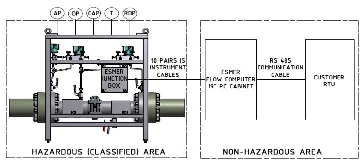
Multiphase Flow Meter MPFM BLOCK DIAGRAM