


- Home
- Oilfield Equipment CATALOGUE
- Wellhead & Christmas Tree
- Well Control Equipment
- Mud Logging Unit
- Mud Pump & Spares
- Top Drive Drilling Equipment
- Formation tester
- Multiphase-Flow-Meter(MFM)
- New Research & Design Tools
- Blade Retrievable New-type Scraper (Patent product)
- Down-hole Safety Valve
- Dual Reverse Circulating Valve
- Full bore Pressure Controlled Select Tester Valve
- New-type Dual Sealing Multi-function Hydraulic Packer (Patent product)
- New-type Dual Sealing Multi-function Mechanical Packer (Patent product)
- New-type MFC Clean & Scrape Integrated Operation Tool and String Selection (Patent product)
- New-type MFC Drill and Scrape Integrated Operation Tool and String Selection (Patent product)
- Wellhead Hydraulic Safety Valve
- Packer
- Well Testing & Completion Tools
- Well Workover Tools
- Wellhead Tools
- Drilling tools
- Casing Bushing And Insert Bowl series
- DG Series Of Hooks
- DWJ-178/250 Power Slips
- Dslseries Power Swivels
- FP sealed anti-spraying boxes
- FSQ Mouse Hole Clamping Device
- Hydraulic Pneumatic Spinner
- JGS-1B Geophysical Well Logging Equipment
- Kelly Spinner
- PZ Series Of Mud Pump
- Pneumatic reversing valve
- Q Series Of Spinning
- QD Pneumatic Casing
- QJ Series Air Winches
- QW Series Drill Pipe Air Slips
- Roller Kelly Bushing
- Rotary Bushing And Insert
- Suspender
- Swivel With Spinner
- TB casing back-up tong
- TC SERIES OF CROWN BLOCKS
- TF Series Of Casing Guides
- TJA Series Casing And Tubing coupling bucking unit
- TJX Series Of Mandrel
- TQ Series Casing Tong
- TS Series Of Hydraulic Riser
- XQ Series of Hydraulic Power Tongs
- YC Series Of Traveling
- YG SERIES OF HOOK BLOCKS
- YJ Series Hydraulic Winches
- YM Series Hydraulic Cathead
- YXM Rotary Cathead
- YZB(YZC) Series Of Hydraulic Power Unit
- ZP Series Of Rotary Tables
- ZQ Drill Pipe Power Tongs
- ZQF216-110 lron roughneck
- ZQJ178 90 drill pipe screwing tong
- ZTQ SERIES DUAL-PURPOSE POWER TONGS
- Drill collars / Drill pipes
- Elevators / Slips / Spiders
- ACCESSORY TOOLS
- CEMENTING TOOLS
- Coring Tools
- DRILL STEM TOOLS
- Arrow Type Back Pressure Valve
- By-pass Valve
- Casing Scraper
- Circulating Sub
- Cup Tester
- Drift
- Drop-In Check Valve
- Fixed Diameter Hole Opener
- Float valve sub
- Full Opening Safety Valve
- Inside BOP
- Integral blade stabilizer
- Kelly Valve
- Key seat Reamer
- Lifting cap and Casing Protector
- Non-rotating Stabilizer
- Oriented Bent sub
- Replaceable Sleeve Stabilizer
- Roller Reamer
- Rotary Sub And Others
- Wear Sub
- Drill Collar
- Drill Pipe
- FISHING TOOLS
- AJ Type Safety Joint
- Cable Fishhook
- Die Collars
- Ditch Magnet
- External Hook
- H Type Safety Joint
- Impression Blocks
- Internal Hook
- Junk Subs
- Lifting-Lowering and Releasing Overshots
- Mechanical External Cutter
- Mechanical Internal Cutter
- Multi-String Cutter
- Releasing Spear
- Releasing and Reversing Overshots
- Reverse Circulation Fishing Magnet
- Reverse Circulation Junk Basket
- Reversing Spear
- Reversing sub
- Section Mill
- Series 20 Overshort
- Series 70 Short Catch Overshot
- Sliding Block Spear
- Standard Fishing Magnet
- Taper Tap
- Washover Pipe
- series 150 overshot
- Integral Heavy Weight Drill Pipe
- JARS TOOLS
- BXJ Lubricated fishing bumper sub
- CSJ Super Fishing Jar
- DJ Surface Bumper Jar
- JYSZ Double Acting Hydraulic-Mechanical Drilling Jar
- KXJ Fishing Bumper Sub
- QJZ Mechanical Drilling Jar
- QYSZ Type Full Hydraulic Drilling Jar
- SJ Double-Way Shock Absorber
- YJ one-way shock absorber
- YSJ Type Z Oil Jar
- ZJS Jar Intensifier
- ZSJ/ZXJ Hydraulic & Mechanical
- Kellys & tool joints
- MILLING TOOLS
- Kelly / Bushings
- Search
- About
- Supply Chain Management
- Global Reach
- Contact
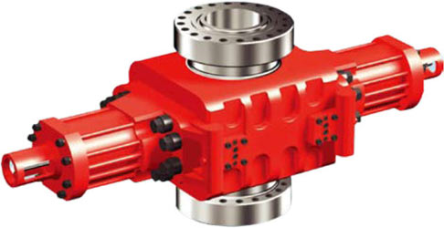
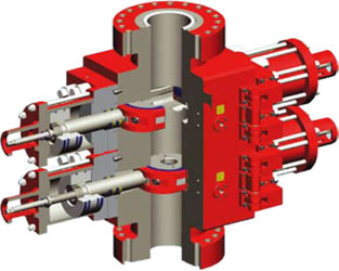
S-Shaped BOP
Our TYPE S Ram BOPs are designed and manufactured according to API Spec 16A standard and GB/T20174 and are equipped with single or double rams from 7 1/16" to 21 1/4" .
Features
- Steel Body and side door.
- Uses floating type ram design. Front ram rubber is separated from top ram rubber, making it more reliable in sealing and easier to change.
- Oil way inside body.
- Loading hinge separate from hydraulic hinge.
- Compact hinge structure makes it easy to assemble and disassemble.
- Arc-shaped body chamber with four round corners as transition section to reduce stress peak value.
- Ram cavity can be fitted with ram assembly of same type BOP made elsewhere.
- Stainless steel lined flange grooves.
Type S BOP Operation Data
| Drift diameter/pressure | Oil quantity for opening the ram (L/set) | Oil quantity for closing the ram (L/set) | Locking mode | Piston diameter, mm | Remarks |
|---|---|---|---|---|---|
| 7 1/16″/5000psi | 1.6 | 1.9 | Manual | 150 | |
| 7 1/16″/10000psi | 2.22 | 2.5 | Manual | 180 | |
| 7 1/16″/15000psi | 7.48 | 85 | Manual | 280 | Allowed to be fitted with a shear ram |
| 9″/3000psi | 1.55 | 1.9 | Manual | 140 | |
| 9″/5000psi | 4.7 | 5.3 | Manual | 220 | |
| 11″/3000psi | 2.68 | 3.22 | Manual | 165 | |
| 11″/5000psi | 5.2 | 5.45 | Manual | 220 | |
| 11″/5000psi | 14.6 | 16.3 | Manual | 355 | Allowed to be fitted with a shear ram |
| 11″/10000psi | 6.6 | 7.4 | Manual | 250 | |
| 11″/15000psi | 14.4 | 16.7 | Manual | 355 | Allowed to be fitted with a shear ram |
| 13 5/8″/5000psi | 7.4 | 8.3 | Manual | 250 | Allowed to be fitted with a shear ram |
| 13 5/8″/10000psi | 19.9 | 20 | Manual | 355 | Allowed to be fitted with a shear ram |
| 13 5/8″/15000psi | 17.44 | 19 | Manual | 355 | Allowed to be fitted with a shear ram |
| 20 3/4″/3000psi | 12.2 | 13.6 | Manual | 250 | |
| 21 1/4″/2000psi | 13.2 | 15.4 | Manual | 250 |
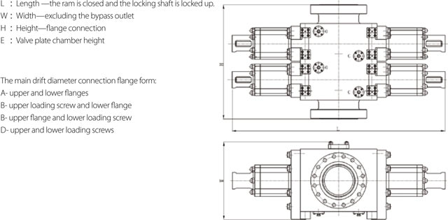
Dimension Schematic of Type S Single Ram BOP
Type S SINGLE RAM BOP
Type S DOUBLE RAM BOP
Dimension Schematic of Type S Single Ram BOP
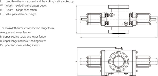
Dimension Schematic of Type S Single Ram BOP
| Size (in.) | Operating pressure (psi) | Vertical drift diameter (in.) | Main drift diameter connection flange form | L (mm) | W (mm) | H (mm) | Weight (Kg) | Remarks |
|---|---|---|---|---|---|---|---|---|
| 7 1/16 | 5,000 | 7 1/16 | A | 1420 | 633 | 624 | 977 | |
| 7 1/16 | 10,000 | 7 1/16 | A | 1720 | 715 | 829 | 2291 | |
| 7 1/16 | 15,000 | 7 1/16 | A | 1842 | 934 | 922 | 3405 | Allowed to be fitted with a shear ram |
| 9 | 3000 | 9 | A | 1700 | 595 | 580 | 1078 | |
| 9 | 5000 | 9 | A | 2036 | 815 | 820 | 2033 | |
| 11 | 3,000 | 11 | A | 2265 | 895 | 802 | 2640 | |
| 11 | 5,000 | 11 | A | 2265 | 820 | 943 | 3646 | |
| 11 | 5,000 | 11 | A | 2363 | 866 | 980 | 3800 | Allowed to be fitted with a shear ram |
| 11 | 10,000 | 11 | A | 2384 | 940 | 1047 | 4067 | |
| 11 | 15,000 | 11 | A | 2640 | 1167.5 | 1244 | 7154 | Allowed to be fitted with a shear ram |
| 13 5/8 | 5,000 | 13 5/8 | A | 2468 | 970 | 950 | 4398 | |
| 13 5/8 | 10,000 | 13 5/8 | A | 3274 | 1488 | 1275 | 9485 | Allowed to be fitted with a shear ram |
| 13 5/8 | 15,000 | 13 5/8 | A | 3074 | 1305 | 1420 | 12035 | Allowed to be fitted with a shear ram |
| 20 3/4 | 3,000 | 20 3/4 | A | 3424 | 1238 | 1070 | 5938 | |
| 21 1/4 | 2,000 | 20 3/4 | A | 3366 | 1205 | 915 | 6605 |
Dimension Schematic of Type S Double Ram BOP
Dimension Schematic of Type S Double Ram BOP
| Size (in.) | Operating pressure (psi) | Vertical drift diameter (in.) | Main drift diameter connection flange form | L (mm) | W (mm) | H (mm) | Weight (Kg) | Remarks |
|---|---|---|---|---|---|---|---|---|
| 7 1/16 | 5,000 | 7 1/16 | A | 1420 | 633 | 910 | 1724 | |
| 7 1/16 | 10,000 | 7 1/16 | A | 1720 | 715 | 1262 | 3520 | |
| 7 1/16 | 15,000 | 7 1/16 | A | 1842 | 934 | 1372 | 6291 | Allowed to be fitted with a shear ram |
| 9 | 3000 | 9 | A | 1700 | 595 | 860 | 2016 | |
| 9 | 5000 | 9 | A | 2036 | 815 | 1200 | 3669 | |
| 11 | 3,000 | 11 | A | 2265 | 895 | 1228 | 4661 | |
| 11 | 5,000 | 11 | A | 2265 | 820 | 1337 | 7022 | |
| 11 | 5,000 | 11 | A | 2363 | 866 | 1470 | 6300 | Allowed to be fitted with a shear ram |
| 11 | 10,000 | 11 | A | 2384 | 940 | 1582 | 6940 | |
| 11 | 15,000 | 11 | A | 2640 | 1167.5 | 1784 | 12686 | Allowed to be fitted with a shear ram |
| 13 5/8 | 5,000 | 13 5/8 | A | 2468 | 970 | 1430 | 7814 | |
| 13 5/8 | 10,000 | 13 5/8 | A | 3274 | 1488 | 1732 | 14582 | Allowed to be fitted with a shear ram |
| 13 5/8 | 15,000 | 13 5/8 | A | 3074 | 1305 | 1985 | 18439 | Allowed to be fitted with a shear ram |
| 20 3/4 | 3,000 | 20 3/4 | A | 3424 | 1238 | 1655 | 14000 | |
| 21 1/4 | 2,000 | 20 3/4 | A | 3366 | 1205 | 1505 | 10435 |
Explosion Drawing of Type S Double Ram BOP
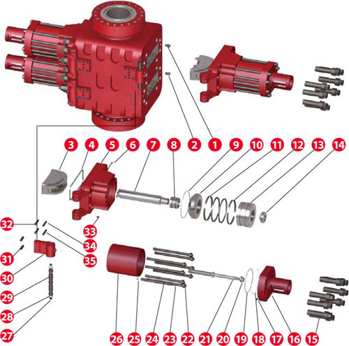
No. of Part Drawing of Type S Double Ram BOP
Taking 2FZ3570-00A for instance
| No. | Part No. | Name | Qty. |
|---|---|---|---|
| 1 | 2FZ3570-01A | Body | 1 |
| 2 | SFZ1310-50 | Pin | 8 |
| 3 | DFZ1310.01E-00 | Blind ram assembly | 2 |
| 4 | SFZ1310.07-00 | Door seal | 4 |
| 5 | SFZ1310-41 | Right door | 2 |
| SFZ1310-26 | Left door | 2 | |
| 6 | SFZ1310-30 | Secondary sealing screw plug | 4 |
| SFZ1310-31 | Sealing grease | 4 | |
| SFZ1310.32-00 | Check valve | 4 | |
| 7 | SFZ1310-09 | Ram shaft | 4 |
| 8 | 2FZ3570.10-00 | Ram shaft sealing assembly | 4 |
| 9 | SFZ1310-47 | O-ring 395×5.7 | 4 |
| 10 | SFZ1310-08 | Locking nut | 4 |
| 11 | SFZ1310-13 | Rubber | 8 |
| 12 | SFZ1310-12 | Wearing ring | 8 |
| 13 | SFZ1310-42 | Piston | 4 |
| 14 | SFZ1310-15 | Locking plate | 4 |
| 15 | SFZ1310-33 | Bolt | 32 |
| 16 | SFZ1310-16 | Cylinder head | 4 |
| 17 | SFZ1310-01 | Screw plug Z3/4" | 40 |
| 18 | SFZ1310-25 | Retainer ring | 4 |
| 19 | SFZ1310-24 | O-ring | 4 |
| 20 | 2FZ3570.11-00 | Locking shaft sealing assembly | 4 |
| 21 | SFZ1310-11 | Locking shaft | 4 |
| 22 | SFZ1310-35 | Nut | 32 |
| 23 | SFZ1310-34 | Cylinder bolt | 32 |
| 24 | SFZ1310-43 | Cylinder manifold | 4 |
| 25 | GB1235-76 | O-ring 38X3.5 | 16 |
| 26 | SFZ1310-10 | Cylinder | 4 |
| 27 | SFZ1310-04 | Screw plug Z1" | 24 |
| 28 | GB1235-76 | O-ring 60X5.7 | 32 |
| 29 | SFZ1310-03 | Hinge pin | 4 |
| 30 | SFZ1310-40 | Right hinge bracket | 2 |
| SFZ1310-05 | Left hinge bracket | 2 | |
| 31 | GB/T118-2000 | Pin 20X110 | 8 |
| 32 | GB/T70.1-2000 | Screw M24X110 | 16 |
| 33 | SFZ1310-49 | Screw plug Z1" (perforated) | 4 |
| 34 | GB1235-76 | O-ring 34×3.5 | 8 |
| 35 | GB1152-89 | Oil cup M10X1 | 4 |