


- Home
- Oilfield Equipment CATALOGUE
- Wellhead & Christmas Tree
- Well Control Equipment
- Mud Logging Unit
- Mud Pump & Spares
- Top Drive Drilling Equipment
- Formation tester
- Multiphase-Flow-Meter(MFM)
- New Research & Design Tools
- Blade Retrievable New-type Scraper (Patent product)
- Down-hole Safety Valve
- Dual Reverse Circulating Valve
- Full bore Pressure Controlled Select Tester Valve
- New-type Dual Sealing Multi-function Hydraulic Packer (Patent product)
- New-type Dual Sealing Multi-function Mechanical Packer (Patent product)
- New-type MFC Clean & Scrape Integrated Operation Tool and String Selection (Patent product)
- New-type MFC Drill and Scrape Integrated Operation Tool and String Selection (Patent product)
- Wellhead Hydraulic Safety Valve
- Packer
- Well Testing & Completion Tools
- Well Workover Tools
- Wellhead Tools
- Drilling tools
- Casing Bushing And Insert Bowl series
- DG Series Of Hooks
- DWJ-178/250 Power Slips
- Dslseries Power Swivels
- FP sealed anti-spraying boxes
- FSQ Mouse Hole Clamping Device
- Hydraulic Pneumatic Spinner
- JGS-1B Geophysical Well Logging Equipment
- Kelly Spinner
- PZ Series Of Mud Pump
- Pneumatic reversing valve
- Q Series Of Spinning
- QD Pneumatic Casing
- QJ Series Air Winches
- QW Series Drill Pipe Air Slips
- Roller Kelly Bushing
- Rotary Bushing And Insert
- Suspender
- Swivel With Spinner
- TB casing back-up tong
- TC SERIES OF CROWN BLOCKS
- TF Series Of Casing Guides
- TJA Series Casing And Tubing coupling bucking unit
- TJX Series Of Mandrel
- TQ Series Casing Tong
- TS Series Of Hydraulic Riser
- XQ Series of Hydraulic Power Tongs
- YC Series Of Traveling
- YG SERIES OF HOOK BLOCKS
- YJ Series Hydraulic Winches
- YM Series Hydraulic Cathead
- YXM Rotary Cathead
- YZB(YZC) Series Of Hydraulic Power Unit
- ZP Series Of Rotary Tables
- ZQ Drill Pipe Power Tongs
- ZQF216-110 lron roughneck
- ZQJ178 90 drill pipe screwing tong
- ZTQ SERIES DUAL-PURPOSE POWER TONGS
- Drill collars / Drill pipes
- Elevators / Slips / Spiders
- ACCESSORY TOOLS
- CEMENTING TOOLS
- Coring Tools
- DRILL STEM TOOLS
- Arrow Type Back Pressure Valve
- By-pass Valve
- Casing Scraper
- Circulating Sub
- Cup Tester
- Drift
- Drop-In Check Valve
- Fixed Diameter Hole Opener
- Float valve sub
- Full Opening Safety Valve
- Inside BOP
- Integral blade stabilizer
- Kelly Valve
- Key seat Reamer
- Lifting cap and Casing Protector
- Non-rotating Stabilizer
- Oriented Bent sub
- Replaceable Sleeve Stabilizer
- Roller Reamer
- Rotary Sub And Others
- Wear Sub
- Drill Collar
- Drill Pipe
- FISHING TOOLS
- AJ Type Safety Joint
- Cable Fishhook
- Die Collars
- Ditch Magnet
- External Hook
- H Type Safety Joint
- Impression Blocks
- Internal Hook
- Junk Subs
- Lifting-Lowering and Releasing Overshots
- Mechanical External Cutter
- Mechanical Internal Cutter
- Multi-String Cutter
- Releasing Spear
- Releasing and Reversing Overshots
- Reverse Circulation Fishing Magnet
- Reverse Circulation Junk Basket
- Reversing Spear
- Reversing sub
- Section Mill
- Series 20 Overshort
- Series 70 Short Catch Overshot
- Sliding Block Spear
- Standard Fishing Magnet
- Taper Tap
- Washover Pipe
- series 150 overshot
- Integral Heavy Weight Drill Pipe
- JARS TOOLS
- BXJ Lubricated fishing bumper sub
- CSJ Super Fishing Jar
- DJ Surface Bumper Jar
- JYSZ Double Acting Hydraulic-Mechanical Drilling Jar
- KXJ Fishing Bumper Sub
- QJZ Mechanical Drilling Jar
- QYSZ Type Full Hydraulic Drilling Jar
- SJ Double-Way Shock Absorber
- YJ one-way shock absorber
- YSJ Type Z Oil Jar
- ZJS Jar Intensifier
- ZSJ/ZXJ Hydraulic & Mechanical
- Kellys & tool joints
- MILLING TOOLS
- Kelly / Bushings
- Search
- About
- Supply Chain Management
- Global Reach
- Contact
MFM Water-In-Oil Meter
Technology Overview
 Multiphase Flow Meter WIO Meter measures the flow rates of individual phases in two-phase oil-water production lines (*). Multiphase Flow Meter WIO is based on a cone differential meter which also acts as a capacitance sensor.
(*) Multiphase Flow Meter WIO measures oil-water mass flow rate as well as water composition.
Multiphase Flow Meter WIO works in the range 0-50% water cut and can tolerate up to 5 % GVF within its accuracy specification. Multiphase Flow Meter WIO is particularly suitable for use in production lines and in the liquid leg of separators. Effect of oil density and temperature is taken into account in the factory calibration of the meter. Field measurements are automatically compensated for changes in oil density and temperature Salinity does not affect the measurement made by Multiphase Flow Meter WIO Meter – which is based on the characterisation of the dielectric property of the fluid – see below.
Multiphase Flow Meter WIO field unit makes two primary measurements which are combined in the flow computer to provide the oil flow rate in mass or volumetric units. The primary measurements are those of dielectric constant (water composition) and differential pressure across the cone (mass flow rate).
Parameters Effecting Water Composition Measurement
 The measurement is based on the characterisation of the dielectric constant of the fluid. The dielectric constant of a material is a measure of its ability to transmit electrical potential energy. A dielectric material has poor conductivity, but it can hold a charge with an applied electric field. Dielectric constant is affected by the following parameters.
Frequency of the applied electric field: The value of the dielectric constant varies with the frequency of the applied electric field, but below 106 Hz the dielectric constant is virtually independent of frequency.
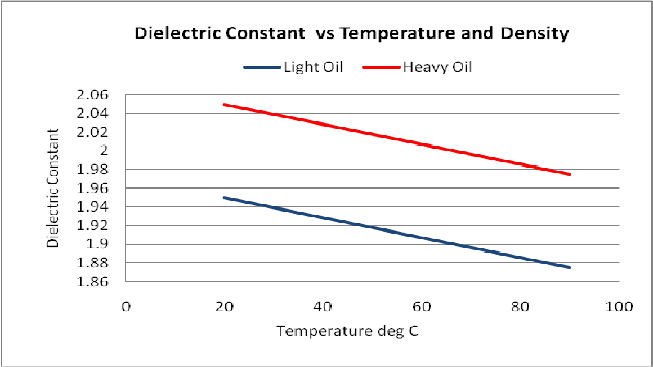
Temperature: Dielectric contant decreases with increasing temperature. The typical decrease in dielectric constant for hydrocarbon oils is about 0.0013 or 0.05% per degree Celsius.
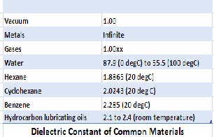 Density: Dielectric constant increases with density. Dielectric will vary in the range 2.0 – 2.4 depending on on API gravity.
Gases: Have relatively small dielectric constants, typically 1.00xx, where xx represents typical variation between gas dielectric constants in the third and fourth decimal places.
Water: has a large and temperature-dependent dielectric constant. Typical decrease in dielectric constant for water is 0.37% per degree Celsius.
Parameters Effecting the Differential Pressure Across the Cone
- The discharge coefficient (determined at the factory loop test) will be affected by any significant changes in the viscosity and density of the fluids in the field.
- Care must be taken to purge trapped gas from the impulse tubes.
- Cone geometry can undergo changes over long period of use.
Accuracy
Chart shows best and worst cases for oil flow rate measurement accuracy (combined error from the two underlying independent measurements of liquid flow rate and water composition).
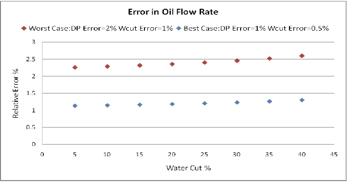 Best case:
- Liquid flow rate: 1 % (relative)
- Water cut : 0.5% (absolute)
Worst case:
- Liquid flow rate: 2 % (relative)
- Water cut : 1% (absolute)
Best and worst case will depend on the mis-match between density and viscosity of the oil phase used for calibration and the fluid in the field.
Specification
 Calibration Inputs (standing data):
- API Density
- Viscosity
Outputs:
The following outputs are provided:
- Liquid flow rate (mass / volume)
- Water composition (volume fraction)
- Oil flow rate (mass / volume)
- Pressure
- Temperature
Operating Envelope
- Water cut : 0 – 40%
- GVF: up to 5 %
- API gravity No limitation (subject to pre-calibration)
- Viscosity 25 – 3000 cp (if it flows it can be measured !)
Limits
- Ambient temperature: -40 to 85°C
- Process temperature: -40 to 120°C
- Process pressure: Maximum 100 bara
Mechanical and Electrical
- Pipe Diameter Customer specification
- Materials: Customer specification
- Flange connections: Customer specification
- Certification: EEx ia IIC T4/T6
- Power Supply: 24 VDC or 110/220 VAC
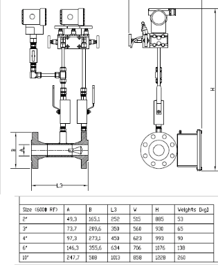
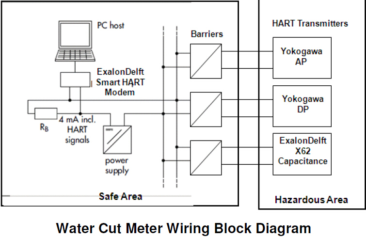
Optimum liquid service installation of Multiphase Flow Meter WIO Meter is shown in the diagram on the right.
Transmitters
Multiphase Flow Meter WIO uses the following oil industry standard transmitters.
- DP Yokogawa
- AP Yokogawa
- Temperature Thermocouple
- Capacitance ExalonDelft X62
Flow Computer
The signals are processed in low power consumption computer installed on the flow line or an industrial PC in the safe area, Measurements can be transmitted via the SCADA interface
- Hazardous Area : Beckhoff CX1010 microprocessor in field enclosure Zone 1
- Safe area: 19” Rack mount industrial PC
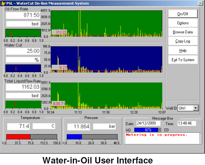
- Software: Multiphase Flow Meter WaterCut Metering Software
- Comms Protocol: Modbus, HART
Software
Multiphase Flow Meter WIO is founded on a user friendly Windows based software package which handles all the data acquisition and measurement tasks (including auto-compensation for field effects of temperature, composition and density). Measurements are displayed in real-time strip charts and saved in a database, Diagnostic and reporting functions are available. Measurements can also be transmitted in analog or digital form via Ethernet and serial ports under a number of protocols.