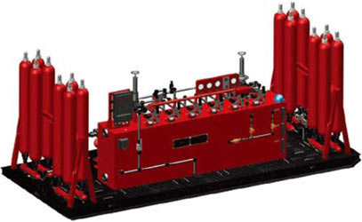
Our pneumatic control systems feature an easy to use driller control panel, four sets of accumulators, a back up oil inlet and splittype accumulator relief valve to ensure simple and reliable operation.
Features
-
Remote control panel is equipped with both electric and pneumatic power.
-
Backup oil inlet ensures system continues operation in unexpected situations.
-
Power system is equipped with automatic control system to protect against overload pressure.
-
Four sets of accumulators which can reliably run at 75% volume in the case of a single failure.
-
Splittype relief valve installed to increase accumulator strength and easy maintenance.
-
Easy to use driller control panel provides clear data on working conditions to reduce chance of misoperation.
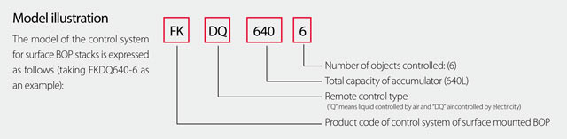
Configuration Parameters of Pneumatic Hydraulic Control System
|
Model |
Number of controlled objects |
Accumulator unit |
Explosionproof motor Power (Kw) |
|
Total volume (L) |
Available liquid volume (L) |
Installation mode |
|
FKQ1600-14 |
14 |
80×20 |
800 |
Side/rear |
18.5×2 |
|
FKQ1600-12 |
12 |
80×20 |
800 |
Side/rear |
18.5×2 |
|
FKQ1600-10 |
10 |
80×20 |
800 |
Side/rear |
18.5×2 |
|
FKQ1440-14 |
14 |
60×24 |
720 |
Side/rear |
18.5×2 |
|
FKQ1280-10 |
10 |
80×16 |
640 |
Side/rear |
18.5×2 |
|
FKQ1280-9 |
9 |
80×16 |
640 |
Side/rear |
18.5×2 |
|
FKQ1280-8 |
8 |
80×16 |
640 |
Side/rear |
18.5×2 |
|
FKQ1280-7 |
7 |
80×16 |
640 |
Side/rear |
18.5×2 |
|
FKQ1200-9 |
9 |
60×20 |
600 |
Side/rear |
18.5×2 |
|
FKQ1200-8 |
8 |
60×20 |
600 |
Side/rear |
18.5×2 |
|
FKQ960-8 |
8 |
60×16 |
480 |
Side/rear |
18.5×2 |
|
FKQ960-7 |
7 |
60×16 |
480 |
Side/rear |
18.5×2 |
|
FKQ800-8 |
8 |
40×20 |
400 |
Side/rear |
18.5 |
|
FKQ 800-7 |
7 |
40×20 |
400 |
Side/rear |
18.5 |
|
FKQ 800-6 |
6 |
40×20 |
400 |
Side/rear |
18.5 |
|
FKQ720-7 |
7 |
60×12 |
360 |
Side/rear |
18.5 |
|
FKQ 720-6 |
6 |
60×12 |
360 |
Side/rear |
18.5 |
|
FKQ 640-6 |
6 |
40×16 |
320 |
Side/rear |
18.5 |
|
FKQ 640-5 |
5 |
40×16 |
320 |
Side/rear |
18.5 |
|
FKQ 480-5 |
5 |
40×12 |
240 |
Side/rear |
18.5 |
|
FKQ 480-4 |
4 |
40×12 |
240 |
Side/rear |
18.5 |
|
FKQ320-5 |
5 |
40×8 |
160 |
Side/rear |
15 |
|
FKQ320-4 |
4 |
40×8 |
160 |
Side/rear |
15 |
|
FKQ320-3 |
3 |
40×8 |
160 |
Side/rear |
15 |
|
FKQ240-3 |
3 |
40×6 |
120 |
Side/rear |
15 |
|
FKQ200-4 |
4 |
25×8 |
100 |
Side/rear |
15 |
|
FKQ160-3 |
3 |
40×4 |
80 |
Side/rear |
15 |
|
FKQ150-2 |
2 |
50×3 |
75 |
Side/rear |
15 |
|
FK125-3 |
3 |
25×5 |
62.5 |
Side/rear |
7.5/11 |
|
FK80-3 |
3 |
40×2 |
40 |
Side/rear |
7.5 |
|
FK80-2 |
2 |
40×2 |
40 |
Side/rear |
7.5 |
|
FK75-2 |
2 |
25×3 |
62.5 |
Side/rear |
7.5 |
|
FK63-2 |
2 |
63×1 |
31.5 |
Side/rear |
7.5 |
|
FK50-2 |
2 |
25×2 |
25 |
Side/rear |
7.5 |
|
FK40-2 |
2 |
40×1 |
20 |
Side/rear |
7.5 |
|
FK25-2 |
2 |
25×2 |
12.5 |
Side/rear |
7.5 |
|
FK25-1 |
1 |
25×2 |
12.5 |
Side/rear |
7.5 |
|
Model |
Pump system displacement |
Rated operating pressure of the system (Mpa) |
Maximum operating pressure of the system (Mpa) |
|
Triplex pump (mL/r) |
Pneumatic pump (mL/ stroke) |
|
FKQ1600-14 |
80×2 |
120×4 |
21 |
31.5 |
|
FKQ1600-12 |
80×2 |
120×4 |
21 |
31.5 |
|
FKQ1600-10 |
80×2 |
120×4 |
21 |
31.5 |
|
FKQ1440-14 |
80×2 |
120×4 |
21 |
31.5 |
|
FKQ1280-10 |
80×2 |
120×3 |
21 |
31.5 |
|
FKQ1280-9 |
80×2 |
120×3 |
21 |
31.5 |
|
FKQ1280-8 |
80×2 |
120×2 |
21 |
31.5 |
|
FKQ1280-7 |
80×2 |
120×2 |
21 |
31.5 |
|
FKQ1200-9 |
80×2 |
120×3 |
21 |
31.5 |
|
FKQ1200-8 |
80×2 |
120×2 |
21 |
31.5 |
|
FKQ960-8 |
80×2 |
120×2 |
21 |
31.5 |
|
FKQ960-7 |
80×2 |
120×2 |
21 |
31.5 |
|
FKQ800-8 |
80 |
120 |
21 |
31.5 |
|
FKQ 800-7 |
80 |
120 |
21 |
31.5 |
|
FKQ 800-6 |
80 |
120 |
21 |
31.5 |
|
FKQ720-7 |
80 |
120 |
21 |
31.5 |
|
FKQ 720-6 |
80 |
120 |
21 |
31.5 |
|
FKQ 640-6 |
80 |
120 |
21 |
31.5 |
|
FKQ 640-5 |
80 |
120 |
21 |
31.5 |
|
FKQ 480-5 |
80 |
120 |
21 |
31.5 |
|
FKQ 480-4 |
80 |
120 |
21 |
31.5 |
|
FKQ320-5 |
60 |
120 |
21 |
31.5 |
|
FKQ320-4 |
60 |
120 |
21 |
31.5 |
|
FKQ320-3 |
60 |
120 |
21 |
31.5 |
|
FKQ240-3 |
60 |
120 |
21 |
31.5 |
|
FKQ200-4 |
60 |
120 |
21 |
31.5 |
|
FKQ160-3 |
60 |
120 |
21 |
31.5 |
|
FKQ150-2 |
60 |
120 |
21 |
31.5 |
|
FK125-3 |
28 |
- |
21 |
21 |
|
FK80-3 |
28 |
- |
21 |
21 |
|
FK80-2 |
28 |
- |
21 |
21 |
|
FK75-2 |
28 |
- |
21 |
21 |
|
FK63-2 |
28 |
- |
21 |
21 |
|
FK50-2 |
28 |
- |
21 |
21 |
|
FK40-2 |
28 |
- |
21 |
21 |
|
FK25-2 |
28 |
- |
21 |
21 |
|
FK25-1 |
28 |
- |
21 |
21 |
Main Technical Parameters of Pneumatic Hydraulic Control System
|
Normal pressure of the system: |
21 Mpa |
3000 psi |
|
Pressure regulating range of the system: |
0~14 Mpa |
3000 psi |
|
Nitrogen charging pressure of accumulator: |
7±0.7 Mpa |
3000 psi |
|
Pressure switch setting range: |
18.9~21 Mpa |
2700~3000psi |
|
Hydraulic/pneumatic switch setting range: |
18.9~21 Mpa |
2700~3000psi |
|
Air supply pressure: |
0.65~0.8 Mpa |
93~115psi |
|
Power supply: |
380±19V / 50Hz
Optional as required by customers |
|
|
Control power supply: |
24V DC |
|
|
Battery capacity: |
10Ah |
|
|
Communication interface: |
Profibus-Dp |
|
Functional Configuration of Electric Hydraulic Control System
|
Model |
Electric oil pump |
Pneumatic oil pump |
Manual oil pump |
Alarm device |
Standby nitrogen system |
Protection house |
|
FKQ1600-14 |
• |
• |
◊ |
◊ |
◊ |
• |
|
FKQ1600-12 |
• |
• |
◊ |
◊ |
◊ |
• |
|
FKQ1600-10 |
• |
• |
◊ |
◊ |
◊ |
• |
|
FKQ1440-14 |
• |
• |
◊ |
◊ |
◊ |
• |
|
FKQ1280-10 |
• |
• |
◊ |
◊ |
◊ |
• |
|
FKQ1280-9 |
• |
• |
◊ |
◊ |
◊ |
• |
|
FKQ 1280-8 |
• |
• |
◊ |
◊ |
◊ |
• |
|
FKQ1280-7 |
• |
• |
◊ |
◊ |
◊ |
• |
|
FKQ1200-9 |
• |
• |
◊ |
◊ |
◊ |
• |
|
FKQ1200-8 |
• |
• |
◊ |
◊ |
◊ |
• |
|
FKQ960-8 |
• |
• |
◊ |
◊ |
◊ |
• |
|
FKQ960-7 |
• |
• |
◊ |
◊ |
◊ |
• |
|
FKQ800-8 |
• |
• |
◊ |
◊ |
◊ |
• |
|
FKDQ 800-7 |
• |
• |
◊ |
◊ |
◊ |
• |
|
FKQ 800-6 |
• |
• |
◊ |
◊ |
◊ |
• |
|
FKQ720-7 |
• |
• |
◊ |
◊ |
◊ |
• |
|
FKQ 720-6 |
• |
• |
◊ |
◊ |
◊ |
• |
|
FKQ 640-6 |
• |
• |
◊ |
◊ |
◊ |
• |
|
FKQ 640-5 |
• |
• |
◊ |
◊ |
◊ |
• |
|
FKQ 480-5 |
• |
• |
◊ |
◊ |
◊ |
• |
|
FKQ 480-4 |
• |
• |
◊ |
◊ |
◊ |
• |
|
FKQ320-5 |
• |
• |
◊ |
◊ |
◊ |
• |
|
FKQ320-4 |
• |
• |
◊ |
◊ |
◊ |
• |
|
FKQ320-3 |
• |
• |
◊ |
◊ |
◊ |
• |
|
FKQ240-3 |
• |
• |
◊ |
◊ |
◊ |
• |
|
FKQ200-4 |
• |
• |
◊ |
◊ |
◊ |
• |
|
FKQ160-3 |
• |
• |
◊ |
◊ |
◊ |
• |
|
FKQ150-2 |
• |
• |
◊ |
◊ |
◊ |
• |
|
FK125-3 |
• |
x |
◊ |
◊ |
◊ |
• |
|
FK80-3 |
• |
x |
◊ |
◊ |
◊ |
• |
|
FK80-2 |
• |
x |
◊ |
◊ |
◊ |
• |
|
FK75-2 |
• |
x |
◊ |
◊ |
◊ |
• |
|
FK63-2 |
• |
x |
◊ |
◊ |
◊ |
• |
|
FK50-2 |
• |
x |
◊ |
◊ |
◊ |
• |
|
FK40-2 |
• |
x |
◊ |
◊ |
◊ |
• |
|
FK25-2 |
• |
x |
◊ |
◊ |
◊ |
• |
|
FK25-1 |
• |
x |
◊ |
◊ |
◊ |
• |
|
Model |
Insulated House |
Driller’s console |
Auxiliary console |
Pipe rack and hose |
Zero pressure starting system |
|
FKQ1600-14 |
◊ |
• |
◊ |
◊ |
◊ |
|
FKQ1600-12 |
◊ |
• |
◊ |
◊ |
◊ |
|
FKQ1600-10 |
◊ |
• |
◊ |
◊ |
◊ |
|
FKQ1440-14 |
◊ |
• |
◊ |
◊ |
◊ |
|
FKQ1280-10 |
◊ |
• |
◊ |
◊ |
◊ |
|
FKQ1280-9 |
◊ |
• |
◊ |
◊ |
◊ |
|
FKQ 1280-8 |
◊ |
• |
◊ |
◊ |
◊ |
|
FKQ1280-7 |
◊ |
• |
◊ |
◊ |
◊ |
|
FKQ1200-9 |
◊ |
• |
◊ |
◊ |
◊ |
|
FKQ1200-8 |
◊ |
• |
◊ |
◊ |
◊ |
|
FKQ960-8 |
◊ |
• |
◊ |
◊ |
◊ |
|
FKQ960-7 |
◊ |
• |
◊ |
◊ |
◊ |
|
FKQ800-8 |
◊ |
• |
◊ |
◊ |
◊ |
|
FKDQ 800-7 |
◊ |
• |
◊ |
◊ |
◊ |
|
FKQ 800-6 |
◊ |
• |
◊ |
◊ |
◊ |
|
FKQ720-7 |
◊ |
• |
◊ |
◊ |
◊ |
|
FKQ 720-6 |
◊ |
• |
◊ |
◊ |
◊ |
|
FKQ 640-6 |
◊ |
• |
◊ |
◊ |
◊ |
|
FKQ 640-5 |
◊ |
• |
◊ |
◊ |
◊ |
|
FKQ 480-5 |
◊ |
• |
◊ |
◊ |
◊ |
|
FKQ 480-4 |
◊ |
• |
x |
◊ |
◊ |
|
FKQ320-5 |
◊ |
• |
◊ |
◊ |
◊ |
|
FKQ320-4 |
◊ |
• |
x |
◊ |
◊ |
|
FKQ320-3 |
◊ |
• |
x |
◊ |
◊ |
|
FKQ240-3 |
◊ |
• |
x |
◊ |
◊ |
|
FKQ200-4 |
◊ |
• |
x |
◊ |
◊ |
|
FKQ160-3 |
◊ |
• |
x |
◊ |
◊ |
|
FKQ150-2 |
◊ |
• |
x |
◊ |
◊ |
|
FK125-3 |
◊ |
x |
◊ |
◊ |
◊ |
|
FK80-3 |
◊ |
x |
◊ |
◊ |
◊ |
|
FK80-2 |
◊ |
x |
◊ |
◊ |
◊ |
|
FK75-2 |
◊ |
x |
◊ |
◊ |
◊ |
|
FK63-2 |
◊ |
x |
◊ |
◊ |
◊ |
|
FK50-2 |
◊ |
x |
◊ |
◊ |
◊ |
|
FK40-2 |
◊ |
x |
◊ |
◊ |
◊ |
|
FK25-2 |
◊ |
x |
◊ |
◊ |
◊ |
|
FK25-1 |
◊ |
x |
◊ |
◊ |
◊ |
Note:
-
Listed above are basic configurations of our products, where, “•” represents basic configuration and “◊” optional.
-
The optional configuration here doesn’t mean that it is available in any model, which should be discussed at time of contract conclusion.
-
Protection room width: 2100mm for common room and 2300mm for room with thermal insulation.
-
Listed above are basic configurations, but special design and manufacturing can be provided upon request.
-
The auxiliary driller’s console can be based on buttons or touch screen
-
Pneumatic pump is not available to FKDQ series liquid control equipment. The remote console must be provided with air supply interface for pneumatic control.